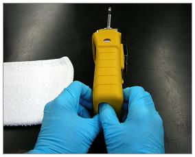
The MiniRAE 2000 fits snugly in its protective yellow boot. Remove the protective yellow boot by hooking your fingers inside the front and back holes in the boot. Pull outward on the boot with your fingers while pushing up on the bottom of the MiniRAE 2000 with your thumbs.
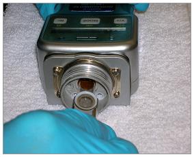
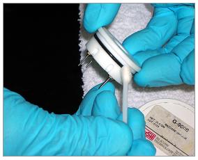
Remove the lamp housing cap by turning it counter-clockwise. Once removed, the entire sensor adapter/sample probe assembly can be removed from the lamp housing.
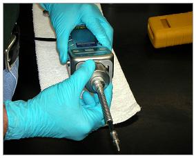
Remove the lamp housing cap from the sensor adapter/sample probe assembly.
Invert the sensor adapter/sample probe assembly. Remove the porous metal filter cap by turning it counter-clockwise. Remove the porous metal filter. Tap the filter on a hard, dark surface. Replace the filter if any particulates fall away from the porous metal filter. Do not discard the dirty porous metal filter. It can be cleaned in an ultrasonic bath (described later) and re-used repeatedly.

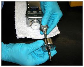
Invert the sensor adapter/sample probe assembly. Remove the sample probe by turning the knurled nut at the bottom of the probe counter-clockwise.
Remove the white, fibrous particulate filter from the sensor adapter. This filter is optional, but provides a disposable pre-filter before the porous metal filter. This filter should be changed whenever it appears soiled or more often, if working with moist samples. A clogged filter can impede sample flow. A moist filter can trap VOC's and give a false positive reading.
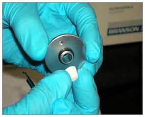
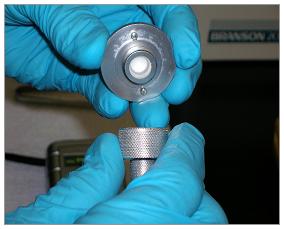
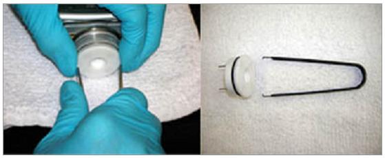
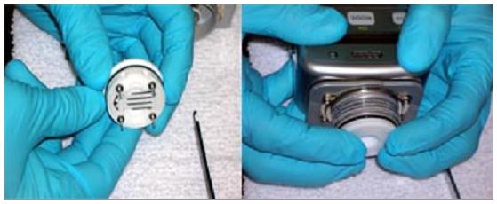
Use the sensor removal tool to remove the sensor from the lamp housing. The photo on the right illustrates how the hooks on the tool are designed to go around and grasp the upper edge of the sensor. The sensor is made of Teflon® and is very soft. Great care must be used to remove the sensor without having the steel hooks of the tool gouge the sensor, should the tool slip. The photo on the left illustrates the method to use to prevent this from happening. Place the tool hooks around the edge of the sensor so that they are at the 3 o'clock and 9 o'clock positions. Then, use the thumb and index finger of your weak-side hand to hold the hooks in place. Gently wiggle and pull the sensor out of the lamp housing by pulling with your strong-side hand. DO NOT TOUCH THE METAL SENSOR ELECTRODES ON THE BOTTOM OF THE SENSOR!
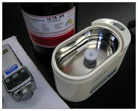
Periodically clean the porous metal filter and the sensor in an ultrasonic cleaner using reagent-grade methanol. The porous metal filter should be cleaned whenever particulates fall away from the filter when it is tapped on a hard, dark surface or if water has been drawn into the sensor, but not the instrument or pump. The sensor should be cleaned whenever the MiniRAE 2000 exhibits any of the following symptoms:
- The instrument will not zero and/or span properly.
- The instrument display reading climbs steadily when there are no VOC's present.
- The instrument display reading climbs steadily in the presence of moisture.
- Water has been drawn into the sensor, but not into the instrument or pump.
Fully submerse the porous metal filter and/or sensor in reagent-grade methanol, run the ultrasonic cleaner through two cycles, remove the porous metal filter and/or sensor, carefully shake off the excess methanol, then allow the porous metal filter and/or sensor to air-dry overnight.
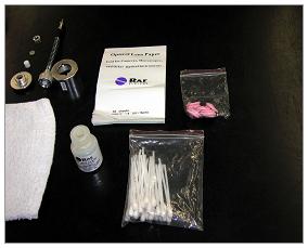
This photo illustrates the items that are shipped from RAE Systems for cleaning the lamp. You may substitute materials that you already have at your office. Note that nitrile gloves are being used in these photos instead of the small pink finger cots.
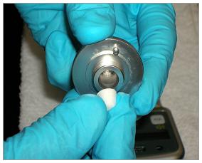
Use the sensor removal tool to gently pull the lamp out of the lamp housing. Use the hooks on the tool to grab the Teflon® o-ring at the lens end of the lamp.
Gently grasp the PID lamp while wearing gloves or finger cots. Moisten a cotton swab with reagent-grade methanol. Gently clean the lens of the PID lamp. The trace methanol on the lens will evaporate readily. Wipe the lamp with lens cleaning paper to ensure that it is dry and oil-free.
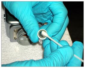
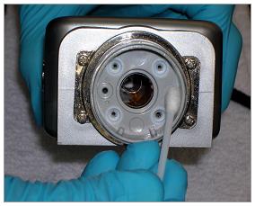
Use a clean, dry cotton swab to remove any particulates that have accumulated in the lamp housing.
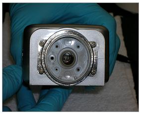
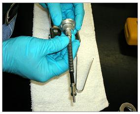
Reinsert the PID lamp in the lamp housing. The spring in the lamp receptacle will usually cause the lamp to protrude approximately 1/4" from the base of the lamp housing.
Apply a very thin film of silicone grease to the o-ring on the PID sensor. This will allow for easy insertion and removal of the PID sensor from the lamp housing and will prevent the sensor from becoming stuck in the lamp housing.
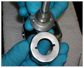
Carefully inspect the PID sensor before reinserting it into the lamp housing. The metal sensor electrodes on the bottom of the sensor should be flat, straight, and parallel. They should not be touching the Teflon® portion of the sensor. They should not be corroded or discolored. The nuts on the four sensor pins should be snug, but not too tight. Note that one of the four pins is larger than the other three and that the sensor has two notches in the cylindrical side of the sensor. These two notches correspond to the two tabs in the lamp housing that control the positioning of the sensor when it is reinserted. Align the notches and tabs and use four evenly placed fingers to push the sensor straight into the lamp housing until it is fully seated.
Insert a new cotton filter into the tapered side of the sensor adapter.
Invert the sensor adapter and replace the porous metal filter. Secure the porous metal filter in place with the filter cap, turning it clockwise until it is finger-tight only.
Invert the sensor adapter and replace the sample probe assembly by turning the knurled nut at the bottom of the probe clockwise until it is finger-tight.
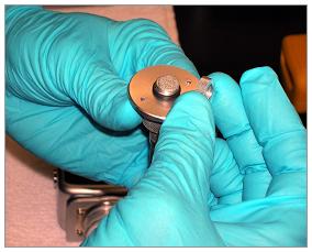
This photo illustrates the assembled sensor adapter/sample probe assembly at the top and the lamp housing cap at the bottom. Note that the sensor adapter has two metal studs that are designed to align with the corresponding slots in the lamp housing cap. The easiest way to reassemble these components to the instrument is to do so as an assembled unit, as demonstrated in the next photo.
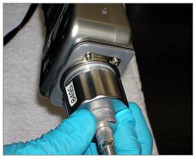
Insert the sensor adapter/sample probe assembly into the lamp housing cap. Align the two metal studs with the corresponding slots and use the fingers of one hand to hold the assembled components tightly together. Use the other hand to rotate the MiniRAE 2000 clockwise until the lamp housing cap is finger-tight and fully seated on the lamp housing.
Turn the MiniRAE 2000 on and check for proper operation of the lamp and the pump stall alarm feature. Momentarily block the sample probe with your fingertip while the pump is running. The audible and visual alarms should come on indicating that the pump is blocked. Remove your fingertip and acknowledge the alarm by pressing the Y/+ tactile pad. Perform the calibration procedure described in the instruction manual to ensure accurate performance.