The Grundfos Redi-Flo 2 Submersible Pumps provides optimal performance when used to pump crystal-clear ground water from a 2" monitoring well with the pump placed well off the bottom of the well and within the screened interval of the well casing. Say what? How many times is the pump actually used in the environmental consulting arena under all, or even any, of these conditions? That's right – rarely. That's why proper use, care, and maintenance of the pump are vital to ensure a reasonable service life from a significant capital investment.
The Grundfos Redi-Flo 2 Submersible Pump depends upon water flowing past the pump stator housing and water within the pump stator housing to keep the bearings cool and the motor windings from swelling due to heat build-up. Routine performance of the following procedures will help prolong the life of the pump and provide for optimum performance.
We have provided the following photographs and procedures to assist you in either the care and maintenance of your pump or of one of EEI's rental pumps that you may use on a long-term project.
If necessary, refer to the pump schematic provided at the end of these procedures for part name or assembly order.
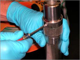
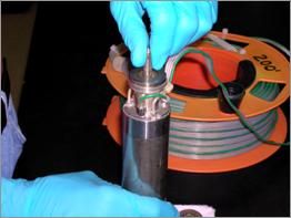
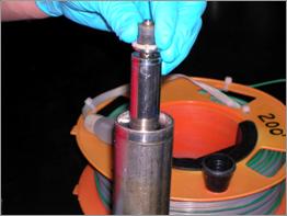
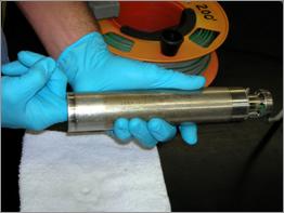
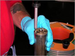
Use a small blade screwdriver to remove the pump screen set screw.
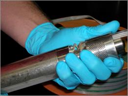
Grasp the pump firmly and gently slide the screen up and off of the pump. Be careful not to cut or score the pump motor lead in the process. If necessary, create a little slack in the motor lead by pushing the motor lead down behind the screen.
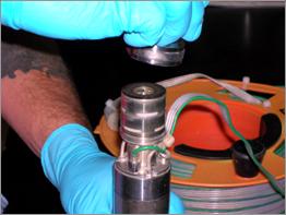
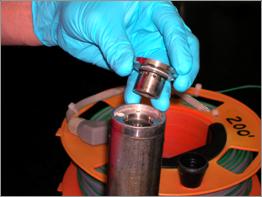
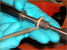
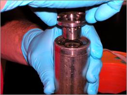
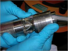
Remove the pump housing by turning it counter-clockwise. Note that the impellers, wear plates, and spacer rings may not stay in place on the pump, as shown in the photo.
Remove the impellers, wear plates, and spacer rings from the rotor shaft.
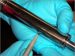
Grasp the rotor and rotate it back and forth. It should turn effortlessly in the stator housing.
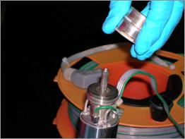
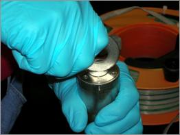
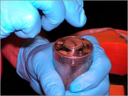
Invert the pump and use a large stainless steel flat washer to remove the filling screw on the bottom of the stator. A large blade screwdriver will tend to slip within the recess in the head of the screw.
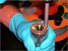
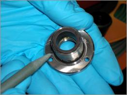
Use a 2.5 mm hex-head driver bit or Allen ® wrench to remove the three short motor screws from the bearing housing in the bottom of the stator housing.
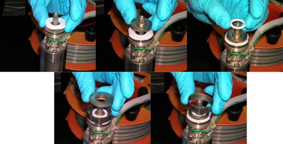
While still holding the pump inverted, gently tap the rotor shaft, at the top of the pump on a hard surface to push the bearing housing up and out of the stator housing.
Push the rotor up and out of the stator housing. The water that is in the stator housing will flow out of the pump once the rotor shaft clears the seal in the upper bearing housing.
The rotor has a bearing and Teflon ® motor thrust washer at each end. The motor thrust washers are captive when new, but will wear over time to where they will come off the bearing. When removing the rotor from the stator housing, ensure that the upper motor thrust washer does not stay lodged in the upper bearing housing. If so, a gentle tap on a hard surface will make it fall out. Inspect the bearing for cracks. It is normal for the surface of the bearing to look mottled over time. It is also normal for the end of the bearing to have a bubbled, gold-colored appearance. If either bearing is cracked, the pump is damaged beyond repair.
Inspect the body of the rotor for rotational wear due to abrasion against the inside of the stator housing. Under normal circumstances, the surface of the rotor body will be smooth, shiny, and abrasion-free. If there are signs of rotational wear, this indicates that there may be swelling of the coils inside the stator housing. This occurs due to over-heating of the pump.
Inspect the bearing housing for cracks in the bushing. If a crack occurs, a semi-circular piece will usually break away from the bushing. If this occurs, the pump is damaged beyond repair.
Insert your index finger into the bottom of the stator housing and feel around the inside of the stator housing for swelling of the motor coils. This occurs due to over-heating of the pump. This can occur gradually over time or very suddenly if the pump is run dry. Eventually, the swelling of the coils will cause the rotor to bind within the stator housing and either inhibit the performance of the pump or render it unusable. Rotational wear of the rotor body is caused by contact with swollen motor coils. In severe cases, the swelling will be so bad that the rotor cannot be removed from the stator housing. If this occurs, the pump is damaged beyond repair.
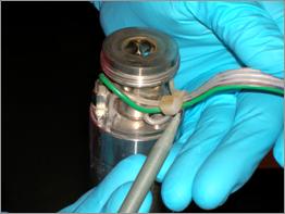
Inspect the motor lead connections at the pump. Look for exposed wire strands where contact with the suction inter-connector, pump housing, or inlet screen have worn through the Teflon ® jacket of the motor lead. Use a clean soldering iron to melt Teflon ® back over the exposed wire strands to repair minor nicks or worn spots. In severe cases of jacket damage, or in the case of complete wire separation, the pump will have to be re-wired.
Re-insert the rotor into the stator housing. Ensure that the top motor thrust washer stays in place on the upper rotor bearing.
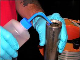
Fill the water cavity of the stator housing with distilled water until the cavity is over-flowing. After doing so, observe the top of the pump while holding it inverted. If more than the occasional drop of water is dripping from the top of the pump, the lip seal needs to be replaced.
Hold the pump firmly with an index finger on each end of the rotor shaft. Slowly move the rotor shaft up and down approximately 3/4" to displace air that is trapped in the water cavity of the stator housing. Top off the level in the water cavity with distilled water and repeat these steps until all air is displaced from the water cavity, as evidenced by the water level not going down when the rotor shaft is moved up and down.
Line up the three holes in the bearing housing with the corresponding three holes in the stator housing. Gently insert the bearing housing into the stator housing until it is almost flush with the bottom of the stator housing. Allow the bearing housing to displace the excess water from the water cavity of the stator housing.
Replace the three short motor screws. Gently tighten them, using a 2.5 mm hex-head driver bit or Allen ® wrench, until you begin to feel resistance and then move to the next screw. Repeat this procedure, working around to each screw, until the screws are tight. Do not over-tighten these screws! The softer stainless steel of the hex head screw cap or stator housing threads can easily strip! This step will continue to displace excess water from the water cavity of the stator housing.
Observe that the water level within the water cavity of the stator housing is to the top of the bearing housing. If not, top off the level with distilled water. Insert the filling screw and gently tighten it with a large stainless steel flat washer until it is flush with the bearing housing.
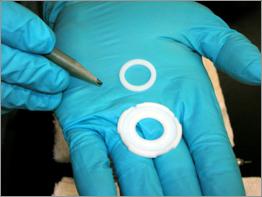
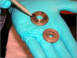
Inspect the Teflon ® wear plates and wear rings for excessive wear. When new, the wear plates and wear rings are approximately 1/8” thick. They should be replaced once you are able to see through them.
Inspect the stainless steel impellers and guide vanes for excessive wear and/or the presence of coarse sand particles and PVC shavings lodged inside the impellers or guide vanes. New impellers and guide vanes have sharp, square machined edges. Pumping of water containing coarse fines will “sand blast” these parts and lower the performance of the pump. They should be replaced when the square edges become rounded or when the bottom contact surfaces of the impellers and guide vanes become razor thin.
There are two stages to the pump. Assemble them one at a time on the pump to ensure proper alignment. Replace the wear plate, impeller, wear ring, spacer ring, and guide vane in the order shown. Ensure that the tabs on the lower edge of the spacer ring engage the corresponding slots on the edge of the wear plate. Each stage should be a perfect cylinder when properly assembled.
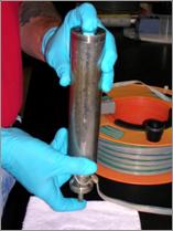
Replace the pump housing, turning it clockwise until finger-tight only.
Gently slide the inlet screen back down over the pump housing being careful to not damage the Teflon ® motor lead jacket.
Use a small blade screwdriver to replace the pump screen set screw.
Test the pump for proper rotation and flow in a 5 gallon bucket that is 3/4 full of clean water. Start the pump at the minimum speed of 25 Hz. Quickly run the pump up to the full 400 Hz capacity of the Variable Speed Drive, and then quickly drop the speed back down to the minimum speed of 25 Hz.