You have finished your assessment and have determined the vertical and lateral extent of impact. Now the real fun begins. What kind of system will I need to clean this mess up? One of the first things to consider is the type of contaminants you have and the chemical properties such as vapor pressure, specific gravity, and solubility. Some other items to be considered before selecting your pilot unit include the following:
- Formation materials encountered while installing wells or soil borings
- Diameter of well installed along with screen length, slot size and placement relative to ground-water level
- Thickness of the contaminated soil based on lab results or OVA readings
- Depth to ground water
- Estimated height of capillary fringe
- Type of fuel released
- Amount of fuel released (rarely an accurate number)
- Has the contaminant reached ground water
- Was bedrock encountered before ground water, after ground water or not at all
For ease of discussion we will assume your site was a corner gas station that had a release of premium unleaded from a dispenser island. Ground water is at 25 feet below ground surface (BGS) and bedrock is at 70 feet. The soil is residual sandy silt, weathered in-place from the parent granite gneiss. Slug test results indicate a hydraulic conductivity of 0.0004 centimeters squared per second. The leak occurred in 2007 at 3 ft BGS and boring data indicated gasoline impacted soil all the way to ground water. The station is active and the leak has been repaired. Excavation is not an option due to the impact on the station's business. Seven monitoring wells were installed including a Type III vertical extent well. The lateral extent of impact is 30 ft by 70 ft and the vertical impact is limited to the upper 55ft of overburden. Tank inventory reports indicate that 6000 gallons of gasoline were lost however separate phase product has not been detected in the wells. Since the leak was in 2007 the gas will not be leaded but will contain MTBE which migrates quickly. We could go on and on with more data but as consultants know you never get all the data you want and typically have to make decisions with limited data.
Since excavation is not an option the next best option is soil vapor extraction (SVE). Why? With hydrocarbon impacted soil present to ground water and ground water impacted as well, clean soil placed in an excavation would become impacted by ground water. SVE is not as invasive, allowing for the station to continue operation during the clean up. SVE typically works well in sands, silty sands, sandy silts and silts. When clayey soil enters the picture, SVE begins to take longer to complete and requires much higher vacuum pressure to achieve the desired results. For our site conditions we will want to us a pilot SVE unit capable of 70-80 inches of water (IWC) vacuum at a flow rate of 80 to 100 SCFM. On a single well test in silty soil you rarely see more than 20 to 50 SCFM of flow from a 10 to 15 foot screened section of a well exposed to unsaturated soil. The idea is to see how much influence you get from testing one well to determine the number of wells and size of the blower you need to clean up the impacted soil. Also, the cost to test just one well is less than testing a whole network of wells before you know if the technology is suitable for your site.
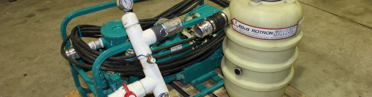
The SVE pilot test unit for this site will likely be a 3 horsepower (HP) to 5 HP 230 Volt Single Phase regenerative blower unit mounted on a skid. A small positive displacement (PD) rotary lobe blower will work fine as well and will typically generate higher vacuum but with lower flow. The unit should be capable of fitting in the back of a standard size pickup truck along with a generator to power the unit. The unit should include an adapter to connect to your well, a hose to run from the unit to the adapter (typically with Cam Lock fittings), a inline moisture knockout tank with a vacuum relief valve and vacuum gage, and explosion proof starter and motor\controls. Magnahelic gages should be connected to the wells surrounding the extraction well to measure the vacuum influence in IWC. The gages closest to the well (no more than 15 to 25 feet away in differing directions) should range from 0 to 10 IWC. Monitoring well points 26 to 50 feet away should use gages with 0-3 IWC range so lower vacuum influence can be detected.
- PILOT TEST EQUIPMENT SELECTION
- PERFORMING THE PILOT TEST
- FULL SCALE EQUIPMENT SELECTION
- BLOWERS: REGENERATIVE, POSITIVE DISPLACEMENT, ROTARY VANE, AND TURBO FANS
- COMPRESSORS: ROTARY SCREW, RECIPROCATING, ROTARY VANE, AND ROTARY CLAW
- PUMPS: CENTRIFUGAL, DIAPHRAGM, PROGRESSIVE CAVITY AND LIQUID RING
- AIR STRIPPERS: TRAY, TOWER, AND TANK
- OIL\WATER SEPARATORS: GRAVITY, COELESSING PLATE, DISSOLVED AIR FLOATATION
- COMPONENTS OF A SOIL VAPOR EXTRACTION SYSTEM
- COMPONENTS OF A DUAL PHASE EXTRACTION SYSTEM
- COMPONENTS OF AN AIR SPARGING SYSTEM
- CHEMICAL INJECTION, RISK BASED CORRECTION ACTION AND NATURAL ATTENUATION