With the pilot test data in hand it is now time to select the equipment for our full scale system. First let's take a look at what we have learned about the site:
- Depth to water 25ft BGS
- K= 0.0001 cm\s
- Formation material = residual sandy silt
- No free product present
- 6000 gallons of gasoline reportedly released
- No underground utilities in the area of the plume
- 1 acre active service station property with the plume area all under pavement
- 208 volt 3 phase power available
- High concentrations of BTEX in vadose soils
- BTEX concentrations in ground water around 30 mg\l
- Sparge radius of influence 20ft with 4 SCFM of air flow at 18 psi
- SVE radius of influence of 50 feet with 40 SCFM air flow at 10" hg vacuum
- The lateral extent of impact is 30 FT by 70 FT and the vertical impact is limited to the upper 55ft of overburden
- Frost depth is 8 inches and freezing weather is expected for several months in the winter and the elevation at the site is 800 FT MSL.
There are numerous ways to clean up this site. Some may suggest chemical injection or a combination of oxidation and bioremediation. In my experience the most cost effective way to remediate a small plume in these soil conditions is with air sparging (AS) and soil vapor extraction (SVE) technologies. Therefore, we will limit our full scale system equipment selection to AS\SVE equipment.
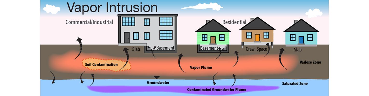
Given the size of our plume and the radiuses of influence determined during pilot testing it appears we need a minimum of 3 SVE wells and 4 sparge wells. Because this is an active station with buildings we are going to overlap our influence areas about 50 percent and go with 4 SVE wells and 6 sparge wells. A general rule of thumb is you want to remove at least 3 times as much air as you inject. You also want to make sure you capture all of the impacted air beneath building to prevent vapor intrusion and sick workers in the buildings. The design flow will be 160 SCFM at 10" hg vacuum (4 wells at 40 SCFM each) for the SVE system. The design for the AS system will be 24 SCFM at 18 psi (six wells at 4 SCFM each). The underground lines to the SVE and AS wells will be designed to reduce friction losses, however, a safety factor should be incorporated into the equipment selection process. The amount of safety factor I use is related to the amount of data I have and quality of that data. Generally, I use a 10 to 20 percent safety factor in addition to selecting equipment to run just above the midpoint of the operating range. This may seem too conservative for some but in my experience the pilot test data is not applicable for the whole site. I would rather have more vacuum or flow than I need than not enough.
Over the years I have grown partial to Ametek Rotron blowers for my SVE systems in the Carolinas. They are not right for every application but have been very reliable for most. However, my choice for this site will be a Roots Dresser rotary lobe positive displacement (PD) blower. In this case, I can achieve the higher vacuum versus low with less horsepower using the PD blower. I am also going to select the gas handling version due to the presence of high concentrations of gasoline vapor in the soil. A modeling program is availing from Enviro-Equipment to help in selection of blowers for SVE and Air sparging as well as other applications. I will discuss pros and cons of several different blower types in PART 4 of this white paper. Due to the explosive nature of gasoline vapor and because we will be installing our system in an enclosed trailer, all components in the SVE room will be rated for Class 1 Division 1 hazards. The SVE system will include a 55 gallon knockout tank with a high level float, a vacuum relief valve, an inline particulate filter, a vacuum bleed valve, an exhaust temperature gauge, an exhaust flow meter (range 0-200 SCFM), a four zone SVE manifold , pressure and vacuum gauges, inlet and exhaust silencers and 2 sample ports.
For the AS system I have selected a rotary claw compressor. I will discuss the pros and cons of several compressor types in PART 4 of this white paper. Claws are generally good to about 30 psi and can produce more flow at the lower pressures than screw compressors or vane compressors. Our sparge pressure is outside the range of most PD blowers. PD blowers that can produce that much pressure would be running at the top end of the performance curve which is not a good thing to do.
Our AS system will include a pressure relief valve, a particulate filter\silencer, a fan cooled after cooler, a pressure bleed valve with muffler, an exhaust temperature gauge, a high temperature shut down switch, a six zone manifold with pressure gauges and 0-10 SCFM flow meters and an interlock solenoid so the AS system will not run unless the SVE system is operational. The air from the claw compressor can get hot.
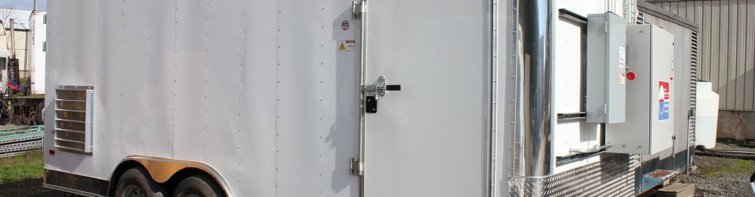
Both systems will be controlled by a single control panel mounted on the front exterior panel of our trailer. The trailer will have 2 rooms. The SVE room will be classed explosion proof and the AS room will be non-explosion proof. Both rooms will have lights and ventilation fans.
Before you say well this section did not tell me much about how to select equipment, take a peek at the outline. I will refer back to the pilot data and my selections in this section as we discuss the pros and cons of each piece of equipment. As far as the accessories that are put in the building or trailer, a lot of those items are personal preferences that can add significant cost to the project. Some of the typical controls will be discussed in other PARTS of this white paper.
- PILOT TEST EQUIPMENT SELECTION
- PERFORMING THE PILOT TEST
- FULL SCALE EQUIPMENT SELECTION
- BLOWERS: REGENERATIVE, POSITIVE DISPLACEMENT, ROTARY VANE, AND TURBO FANS
- COMPRESSORS: ROTARY SCREW, RECIPROCATING, ROTARY VANE, AND ROTARY CLAW
- PUMPS: CENTRIFUGAL, DIAPHRAGM, PROGRESSIVE CAVITY AND LIQUID RING
- AIR STRIPPERS: TRAY, TOWER, AND TANK
- OIL\WATER SEPARATORS: GRAVITY, COELESSING PLATE, DISSOLVED AIR FLOATATION
- COMPONENTS OF A SOIL VAPOR EXTRACTION SYSTEM
- COMPONENTS OF A DUAL PHASE EXTRACTION SYSTEM
- COMPONENTS OF AN AIR SPARGING SYSTEM
- CHEMICAL INJECTION, RISK BASED CORRECTION ACTION AND NATURAL ATTENUATION