To get started with the pilot testing we need to take a look at our site conditions and determine what technology we want to try. Typical technologies used for sites like the one described in Part 1 are Dual Phase Extraction (DPE), Air Sparging (AS), and Soil Vapor Extraction (SVE). There are many different versions of each technology some adding Oxygen or Ozone to the sparged air, some also adding microbes. Due to the absence of free product at our site we are going to try basic AS and SVE technologies and pilot test for each. The vertical extent well will serve as a good pilot test well for the air sparging test because it is located in the hottest part of the plume and it is screened below the vertical extent of impact. Monitoring wells are located within 15 to 35 feet of the well in two directions however the remaining monitoring wells are too far away to use for the pilot test. More wells would be desirable however Consultants typically have to work with a lot less data than they would like to have to keep the cost down and these days to not lose the project to a lower bidder. Most States have Trust Fund programs for Underground Storage Tank (UST) sites a lot of which dictate how long tests can be run and how much you can get paid for it. A whole separate paper could be written on the pros and cons (mostly cons) of these programs but we will leave that alone for now.
A 4-inch diameter well will be installed for the SVE pilot test. The well will be located in the hottest part of the plume that is also closest to as many monitoring wells as possible. The presence or absence of subsurface utilities, product or vent lines, or other short circuit pathways is also considered in choosing the well location. It is also desirable to place the wells in locations that can be used later on when the full scale system is installed.
SVE influence is typically further than the AS influence in the silty residual soils like those found at our site. With 6000 gallons of fuel lost we may see some product appear in some of our wells during or after the test even though none has been measured so far. The SVE well is installed to about 10 feet into water and is screened through the smear zone of impacted soil. The amount of penetration of the water table is decided considering:
- seasonal variation in levels
- time of year the well is installed
- depth of impacted soil
- depth to bedrock
The SVE well is typically screened to within 5 feet of the surface considering the factors mentioned above as well as the presence or absence of surface cover such as asphalt or concrete pavement.
Now that our wells are installed and developed we are ready to get our equipment, supplies and test instruments together for the test. We are going to have about 45ft of water in our sparge well to push out so we know we will need about 20 psi (~2.3ft of water to the PSI) for that plus a little extra to get the flow we want. Normally I limit sparge flow to 4-6 SCFM per well to keep from blowing secondary pathways into the formation that would reduce the effectiveness of sparging. So given that and 20-30 psi pressure needed for the test we decide to use a gasoline powered piston compressor for the sparge air. My preferred compressor would be a rotary claw but that would require a much larger generator. Other compressors can be used as well and the pros and cons of each will be discussed in later sections. As mentioned earlier we are going to use a 3 hp PD blower for the SVE test. Since our depth to water is 25ft BGS we probably don't need a moisture\water knockout tank but we will use it anyway just to be safe. A list of the items we plan to take with us is as follows:
- Roots 22 PD blower \ explosion proof 230v 1 phase motor and controls, with an inline particulate filter, vacuum bleed valve, air sample\velocity measurement port, vacuum gage, pressure gage, inlet scfm flow meter, and 25ft power cord all skid mounted
- 20 gallon moisture knockout tank with cam loc fittings, 5ft 2"ID vacuum truck (VT) hose (blower to knockout), 20ft VT hose (knockout tank to well adapter), and a wellhead adapter with 2" cam loc fitting to 4" fernco fitting and vacuum gage
- 9hp American IMC gasoline power generator with sparge control assembly containing 1 coalescing filter to remove water and 2 oil mist filters in series to remove oil mist from the compressor. The assembly also has a regulator with
pressure gage and a flow meter with flow control. Two quick connect hoses are required. The first hose goes from the compressor to the sparge assembly and the second hose goes from the assembly to the well head. These are made to not be interchangeable so that the hose from the compressor never ends up between the filter\sparge control assembly and the AS well. The reason being this hose could have oil mist in it. 3/8" ID 200 psi rate pressure hose is used. The AS well adapter fitting has a pressure gage and quick connect fitting. The adapter is typically made of schedule 80 PVC and is glued to the well head to prevent it from blowing off during the test. - 12kw generator or plant power if available to run the single phase equipment.
- Two five gallon containers of extra fuel are good to have as well as some simple tools in case a field repair is necessary.
- Instruments including a photo ionization detector (PID) or flame ionization detector (FID), a water level indicator, a dissolved oxygen meter with 50ft cable, an anemometer, a % relative humidity\temperature meter and a 20 liter tedlar bag for air sampling.
- Four magnehelic gauges and well caps\hoses to connect to the monitoring wells. Vacuum ranges for the gauges will be 0-10 inches of water column (IWC) and 0-3 IWC
SVE Test
We begin by connecting the well head adapter to the 4-inch well with the fernco fitting and connecting the cam loc hose to the adapter and the knockout tank. Next we connect the cam loc hose between the knockout tank and the inlet air filter on the blower. The last connection is the power plug to the generator. Before we start the blower we need to open up all the monitoring wells and let them equalize and connect the magnehelic gauges to the monitoring wells to be used in the test. The closest wells will have 0-10 IWC gauges and the furthest wells (35ft) will have 0-3 IWC gages. Two-inch SCH40 PVC caps with barbed fittings are pressed onto the monitoring wells. Clear vinyl tubing is connected to the barb on the cap and to the barb on the back of the gage. The gage is mounted in a small steel stand so it can be placed on the ground by the well. Once the gages are installed an initial set of measurements are recorded and the generator is started. The measurements to be taken and changes made to the SVE system during the 8 hour test are as follows:
- Eight (8) inches of Mercury ("HG) vacuum applied to 4" SVE well for first 2 hours of the test. After 2 hours increase the vacuum to 10"HG for the next 2 hours. Finally set the vacuum to 12"HG for the last 2 to 4 hours of the test.
- Measure the %RH, temperature, air velocity and effluent concentration (PPM) from the SVE stack immediately after starting the blower and every 15 minutes thereafter for the first hour of the test. If air is being bled into the system to reduce the vacuum, take a velocity measurement from the bleed inlet port as well and note the stack and bleed port diameters. This measurement will be subtracted from the stack measurement to determine actual flow from the well. After the first hour measurements should be taken every 30 minutes until the termination of the test. If you are taking air samples for laboratory test this should be done toward the end of the test.
- Record vacuum readings from the monitoring well gauges every fifteen minutes for the first hour and every 30 minutes thereafter for the duration of the test. If no vacuum influence is indicated at the monitoring well after the first 2 hours you should skip the 10" HG vacuum interval and move up to 12"HG for the duration of the test.Before turning the blower off, make sure the bleed air valve (vacuum adjustment) is closed and fill your tedlar bag from the exhaust sample port. Make sure to get the sample to the lab the same day and keep it out of the sun. You should take a PID reading from the exhaust at the same time you are filling the bag to get an idea of the sample concentration. Other air sampling methods such as carbon tubes with sampling pumps or suma canisters can also be used.
In the end you should have data which will tell you whatinfluence you can expect to see from each SVE well and at what vacuum and flow. In addition, when your lab results become available you can determine what your off gas concentration will be for design of an off gas treatment system if required.
Air Sparging Test
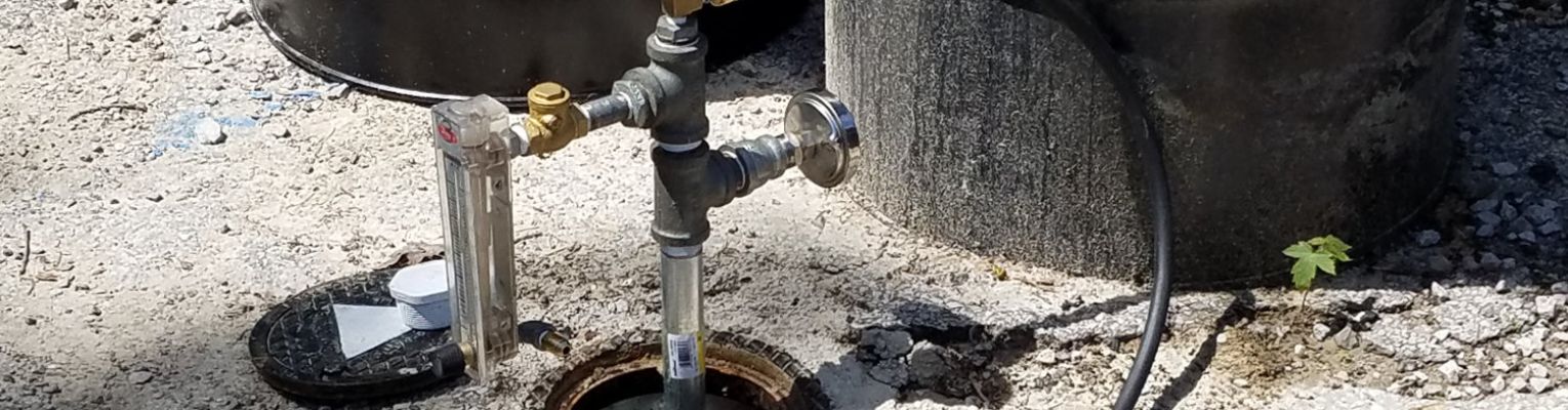
First thing we need to do is glue a 2"slip x 0.75" NPT threaded PVC bushing to the sparge well and open up all the monitoring wells and let them equalize. Next, we will attach a threaded quick connect air fitting to the threaded bushing. An air hose is then connected to the well and the air sparge filter\regulator skid. Next, we connect an air hose from the filter skid to the compressor. Once the hoses are attached an initial set of measurements are recorded and the compressor is started. Make sure you know the pressure capacity of all the materials you will be exposing to air pressure and stay well below the limits. The measurements to be taken and changes made to the SVE system during the 8 hour test are as follows:
Two (2) SCFM of air flow will be applied to 2"AS well for first 2 hours of the test. After 2 hours increase the flow to 4 SCFM for the next 2 hours. Finally set the flow to 6 SCFM for the last 2 to 4 hours of the test. Measure the Dissolved Oxygen (DO) concentration, temperature, head space hydrocarbon concentration, and water level in each well immediately after starting the air flow from the compressor and every 15 minutes thereafter for the first hour of the test. Initially you will have to increase the air pressure a bit to get the water purged from the wells and get the air to begin to flow. The pressure will drop when the air flow begins at which time you adjust the pressure to maintain your first flow setting. After the first hour measurements should be taken every 30 minutes until the termination of the test. If no influence is indicated at the monitoring well after the first 2 hours you should skip the 4 SCFM interval and move up to 6 SCFM for the duration of the test. The flow intervals can be changed as necessary but typically 6-8 SCFM per well is the maximum used. DO NOT TAKE DISSOLVED OXYGEN READINGS IN WELLS THAT CONTAIN FREE PRODUCT AS IT MAY DAMAGE THE PROBE. DO NOT SPARGE A WELL THAT CONTAINS FREE PRODUCT.
Some compressors may require refueling during the test. Caution should be used while doing this as the compressor will be hot. Before turning the compressor off, make sure you have adequate measurements to demonstrate influence. Air sparge influence based on DO and hydrocarbon readings rarely extends more than 20 feet from an injection well. Water level reading may indicate influence much further initially but the mounding affect will dissipate towards the end of the test
Sparge\SVE Combined Test
In some States it is required that a sparge\SVE combination test be performed as well. If you will be performing the combination test it is best do hold off on air samples until this test is performed as the hydrocarbon concentration will likely be higher in the SVE exhaust due to the sparging. The same measurements can be obtained however the vacuum gauge caps will have to be temporarily removed to get the DO, Hydrocarbon and water level measurements. Some people also collect dissolved CO2 measurements during the pilot test but it has been my experience that unless the test is run for a month or longer useful data will not be obtained.
- PILOT TEST EQUIPMENT SELECTION
- PERFORMING THE PILOT TEST
- FULL SCALE EQUIPMENT SELECTION
- BLOWERS: REGENERATIVE, POSITIVE DISPLACEMENT, ROTARY VANE, AND TURBO FANS
- COMPRESSORS: ROTARY SCREW, RECIPROCATING, ROTARY VANE, AND ROTARY CLAW
- PUMPS: CENTRIFUGAL, DIAPHRAGM, PROGRESSIVE CAVITY AND LIQUID RING
- AIR STRIPPERS: TRAY, TOWER, AND TANK
- OIL\WATER SEPARATORS: GRAVITY, COELESSING PLATE, DISSOLVED AIR FLOATATION
- COMPONENTS OF A SOIL VAPOR EXTRACTION SYSTEM
- COMPONENTS OF A DUAL PHASE EXTRACTION SYSTEM
- COMPONENTS OF AN AIR SPARGING SYSTEM
- CHEMICAL INJECTION, RISK BASED CORRECTION ACTION AND NATURAL ATTENUATION